Keys to Successful Flow Measurement: Flow to Perfection
The quality of any measurement depends on the equipment, the user’s understanding of how this equipment works and their ability to create a reproduceable environment that can be studied. Today I would like to have a closer look at some of the factors that contribute to quality ultrasound transit-time (UTT) volume flow measurement.
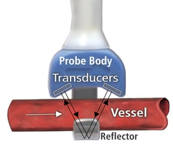
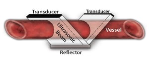
 First, we need to understand how UTT technology works. Transonic UTT flow sensors and probes contain either two transducers with a fixed acoustic reflector or 4 transducers in a X-shaped design. An electrical excitation causes the transducer to emit a plane wave of ultrasound. In the case of our two transducer design, this ultrasonic wave intersects the vessel or tubing under study in the upstream direction, then bounces off the fixed acoustic reflector. It again intersects the vessel and is received by the upstream transducer where it is converted into electrical signals. The same transmit/receive sequence is repeated in the downstream direction. In the case of our “X” design, the opposite transducer directly receives the signal and you have again integrated upstream and downstream signals. The alternating signal sequence happens at frequencies of up to 14.4MHz. The Flowmeter derives and records from this transmit/receive sequence, an accurate measure of the time it takes for the ultrasound signal to travel from one transducer to the other, called the “transit-time.” This is in short, the ‘time component” of UTT technology. A more thorough explanation can be found in our Theory of Operations Technical Note. The next question is, how does the volume component fit into this picture?
 One plane of the ultrasonic beam undergoes a phase shift in transit-time proportional to the average velocity of the liquid times the path length over which this velocity is encountered. The receiving transducer integrates these velocity-chord products over the vessel’s full width and yields volume flow: average velocity times the vessel’s cross-sectional area. Since the transit-time is sampled at all points across the vessel diameter, volume flow measurement is independent of the flow velocity profile.
With this in mind, it is important to understand which factors influence the ultrasound signal and thus your measurements. Temperature of the liquid, type of liquid, other material in the ultrasonic beam all contribute to the overall measurement. Transonic offers two different types of flow sensors, perivascular flow probes designed to be placed around a blood vessel and tubing flow sensors that can either be placed within a tubing line or around a tubing location. Each type of sensor brings with if different consideration, so it makes sense to separate them into groups. Let’s start with our perivascular flow probes.
Perivascular Flowprobes
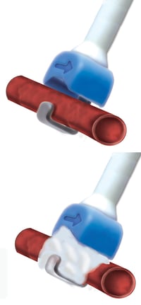
 Ultrasound signals are completely blocked by air, which means that when a perivascular probe is placed around a blood vessel you will have to avoid air bubbles being trapped in between the blood vessel and the probe. This is best done using a couplant called Surgilube (E Fougera & Co.), because Surgilube has the same acoustic properties of blood at 37C. Water and 0.9% saline, commonly used as a stand in for Surgilube, cause reflections of the ultrasound at the vessel boundary. This may lead to changes in the acoustic beam direction in the probe and impose uneven changes in the ultrasound transit-time, causing measurements to be unstable and less accurate. Since perivascular probes are used in vivo you may find fatty tissue around your vessel of interest. It is important to remove the adipose tissue from the area where you want to place the probe because it too can attenuate and otherwise alter the ultrasound signal. Temperature too can have an effect. The speed of the acoustic signal increases with higher temperatures. A difference in temperature between the acoustic couplant and the blood can impose acoustic mismatch and infuses unnecessary confounding variables to the measurement. Keeping the full surgical area at 37C will ensure most stable and accurate data. You will find a detailed document explaining the above in more detail here.
Tubing Flowsensors
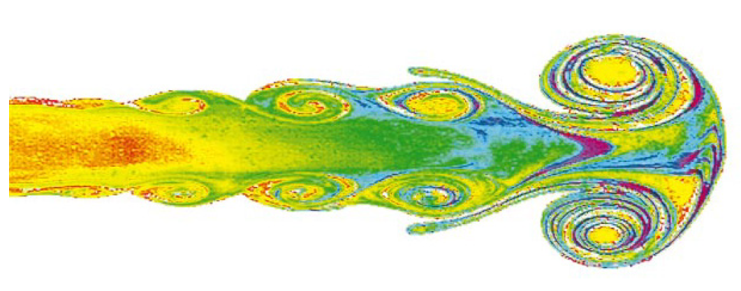
As mentioned in the perivascular flow probes section, all elements that are in the path of the ultrasonic beam will influence the signal and therefore must be factored in during the flow sensor’s calibration. For clamp-on tubing flow sensors, the tubing material itself is the most significant factor, as the ultrasound signal has to go through the tubing material before it reaches the liquid. The angle by which the ultrasound beam reaches the tubing influences how it travels through the tubing and how the signal leaves the tubing and enters the liquid. To make this as uniform over the width of the beam as possible, closed clamp-on sensors slightly flatten the surface on the tubing. This minimizes focusing requirements and variable path lengths of the ultrasound beam, contributing to a more stable and accurate measurement. The second key factor to control is the temperature of the set-up. As described above for the perivascular flow probes, the transition between materials/elements will have the least influence when all material is the same temperature. In the lab it means that it is wise to take your time and have the whole set-up acclimated when you perform your measurements at a different temperature than room temperature.  Flow profiles are another topic to pay attention to. Although Transonic flow sensors have an X-design which makes it possible to measure turbulent flows, accuracy will increase with a laminar stable flow. Transitions from a larger ID to a smaller ID tubing may create vortexes in the liquid, resulting in a potential reading anomalies. In an ideal situation, there is a straight segment of tubing with a length of 10x ID of the tubing before and after the location of the flow sensor. This and more details are described in our technote on tubing flow measurements.
Hopefully the above tips give a helpful starting place when considering the variables that go into quality data collection with our flow sensors. We will plan to cover several more topics related to equipment best practices in future blogs, we hope to see you there. For guidance to choose the correct probe design for your application, we have several documents available but for personal support, you are always welcome to reach out to one of our application specialists directly.


